Hexahedra where accuracy is decided, tetrahedra everywhere else
Structured hexahedral blocks around holes, fillets and shafts, joined to the surrounding tetrahedral mesh through multipoint constraints — and built by temporarily cutting the CAD solid rather than by shoving nodes around.
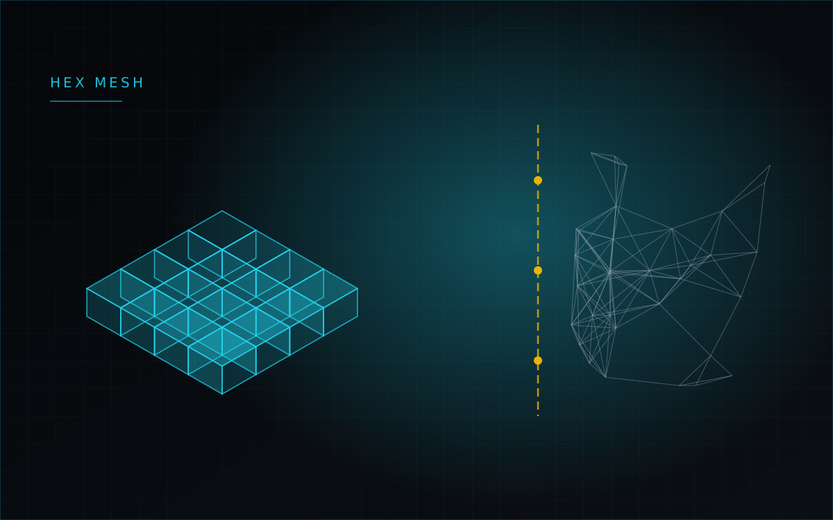
Tetrahedra mesh anything, which is why every automatic mesher produces them. They are also the worst element for bending: first-order tets suffer from shear locking and come out too stiff, and an unstructured tet mesh approximates a curved edge with facets that produce stress peaks belonging to the mesh rather than to the part. The usual remedy is to refine everywhere, which is how a model reaches a million degrees of freedom and stops being interactive.
The alternative is to place structured hexahedral elements exactly where the gradient is, and leave tetrahedra to fill the rest.
Five generators
There are now five structured generators, each for a shape that actually occurs in mechanical parts: a box for blocks and keyways; an annular zone around a hole, with radial grading that follows the 1/r² decay of the classical stress-concentration solution; an O-grid cylinder for bosses and pins, built from a core block and four transfinite sectors so there are no degenerate wedges on the axis; a ribbon along a three-dimensional fillet, carried by a Bishop frame; and a toroidal zone for the junction between a cylinder and a plane, closing a full 360° without duplicated nodes.
All five build both first- and second-order elements. For twenty-node hexahedra the midside nodes are projected analytically onto the true curved boundary — onto the cylindrical arc, the fillet radius or the toroidal surface — rather than left at the midpoint of a chord. Tests check that every element has a strictly positive Jacobian and that volumes converge to the analytical value.
Cut the CAD, don't push the nodes
The first attempt did the obvious thing: mesh the whole part with tetrahedra, delete the elements inside the zone radius, and move the remaining nodes onto the exact radius. It produced inverted elements and visible tears — in an unstructured mesh the boundary nodes are shared with coarse outside tets, and you cannot displace them without remeshing their neighbours.
What works is to cut the solid instead. Before meshing, the pipeline subtracts a tool shape — cylinder, sphere, box or ring — from the CAD body, exports the remainder to STEP, and lets the automatic mesher fill it with tetrahedra against a smooth analytical cavity. The structured hexahedral block is generated separately and dropped into the opening. The user's B-Rep is never modified: this is a temporary decomposition for meshing only, and it costs roughly 50–300 ms of boolean work in the export.
Joining the two
The hexahedral zone and the surrounding tets do not share nodes, so they are tied with multipoint constraints — each slave node's displacement is expressed as a weighted combination of the master face nodes, and the system is reduced accordingly before factorization. The same machinery carries contact between separate bodies in an assembly.
On a real assembly this is what it looks like: 88 bodies, 3,410 second-order hexahedra, 1,106 contact pairs producing 3,318 constraint equations, 74,262 degrees of freedom after reduction — solved on the desktop build in about three seconds, with the constraint error at exactly zero.
- Bodies
- 88
- Constraint equations
- 3,318
- Reduced DOF
- 74,262
- Assembly + reduction
- ~0.95 s
- Factorize + solve
- ~2.1 s
- Constraint error
- 0
Finding the concentrators automatically
A feature scanner can now find the cylindrical holes, fillets and spherical pockets in a model and propose hexahedral zones for them, from the ribbon or from the scripting API. It is a starting point rather than an oracle — you still choose the zone radius and the number of layers.
Honest caveats
Zones must not overlap: two zones whose radii intersect will have their union cut from the solid while the generators still build overlapping elements. A zone should stay clear of the part boundary. The toroidal zone builds correctly and passes its Jacobian checks, but passing its interface faces through to the constraint solver is not finished, and its cutting tool currently has a rectangular section rather than a true swept fillet profile — so micro-corners at the junction with the plane are shaved.
We also do not yet have a measured hexahedra-versus-tetrahedra comparison on the same part — the case for these elements currently rests on theory and on the quality of the generated mesh, not on a number we can show you. Verifying stress concentration factors against the Peterson charts is the next step, and we will publish it when it exists.