Will Your 3D-Printed Part Survive? Check Before You Print, No CAD Needed
A cracked 3D print usually isn't a printing problem — it's a design problem the print revealed. Here's how to run a real stress simulation on your STL in the browser, no CAD software required, before you spend the filament.
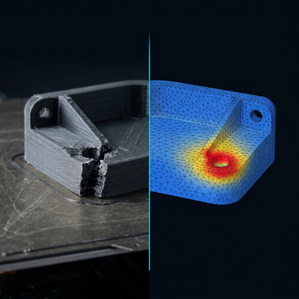
The part that looked fine and snapped anyway
You print a bracket, a mount, a clip. It comes off the bed looking exactly like the model. You screw it in, load it up — and it cracks. Not because the print failed. Because nobody checked, before printing, whether the shape itself could carry the load.
"It printed cleanly" and "it will survive being used" are two completely different claims. A part can have perfect layer adhesion, zero warping, a beautiful finish — and still be geometrically wrong for the forces it's about to see. The failure isn't a printing problem. It's a design problem that printing simply reveals, expensively, after the fact.
The traditional fix for this is finite element analysis (FEA) — the same simulation aerospace and automotive engineers use to predict exactly where a part will break before it's built. The traditional *obstacle* to using it has been that FEA lived inside CAD suites that cost thousands of dollars a year and took a course to learn. That obstacle is gone. You can now run a real stress simulation directly on an STL, in a browser tab, before you commit an hour of filament to a part that was never going to make it.
Why "it looks solid" isn't a real check
Two things make 3D-printed parts specifically bad candidates for eyeballing:
Stress concentrators are invisible to intuition. A hole, a sharp inside corner, a thin wall next to a thick one — each of these creates a local stress spike that can be several times higher than the "average" stress in the part. Your eye reads a bracket as one uniform piece of plastic. The physics doesn't agree: load flows through geometry unevenly, and it always finds the sharpest corner first.
FDM/FFF parts are not uniform in strength. Printed plastic is weaker between layers than within a layer — the bond along the Z-axis is typically the failure plane, not the plastic itself. A part that would be plenty strong if machined from solid stock can fail well below the material's rated strength if the load happens to pull layers apart rather than stretch them. This matters directly for how you read a stress simulation on a printed part — more on that below.
Neither of these shows up by looking at the STL. Both show up immediately on a stress map.
The workflow, step by step
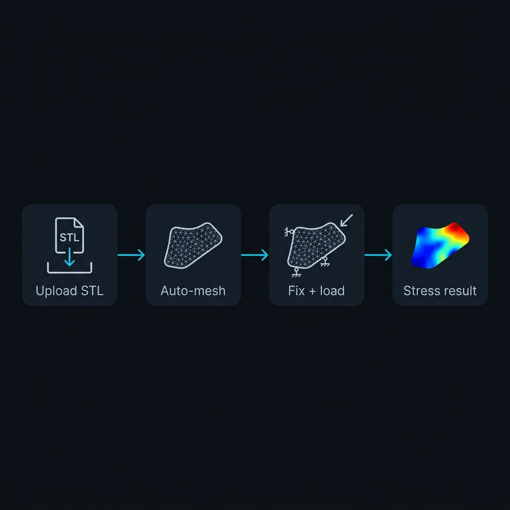
You don't need to build a CAD model from scratch — you already have one, it's the STL (or STEP file) you were about to print.
1. Upload the file. Most browser-based FEA tools accept STL directly, or STEP/IGES if you have the original CAD source (STEP is preferable when available — it preserves exact geometry instead of a triangulated approximation). 2. Let it auto-mesh. The tool breaks the solid into small tetrahedral elements, automatically refining the mesh near holes, fillets, and thin features — the exact places where stress concentrates and where a coarse mesh would miss the real peak. 3. Fix the part where it's actually mounted. Constrain the faces or holes that will be physically held in place — screws, a press-fit, a clamp. Getting this right matters more than almost anything else in the setup: constrain the wrong surface and the whole simulation answers a different question than the one you're asking. 4. Apply the load you actually expect. A force at the point of contact, a distributed pressure, the weight of whatever hangs off it. If you don't know the exact number, estimate on the high side — a rough conservative load beats no load case at all. 5. Run the solve. On a part like this, a linear static solve takes seconds to a couple of minutes, right in the browser tab you already have open. 6. Read the result — not just the color, the numbers. A stress heatmap tells you where the hotspot is. The number that tells you whether you're in trouble is the factor of safety: the ratio between the material's strength and the peak stress the simulation found. Below 1 means it fails in the simulation, let alone in your hand.
Reading the result like it's a 3D print, not a machined part
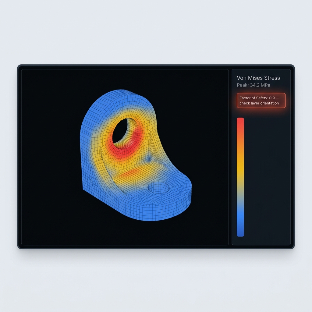
A stress simulation on a printed part is genuinely useful, but it needs one adjustment in how you interpret it: most solvers assume an isotropic material by default — equally strong in every direction, like a block of aluminum. Your printed part isn't. It's weaker along the layer lines than across them.
Two practical ways to use this honestly:
- Treat the factor of safety as a comparison tool, not an absolute guarantee. If two design variants show factor of safety 1.2 and 3.5 under the same load, the second one is meaningfully safer — that comparison holds regardless of the isotropy simplification. Use the simulation to rank designs, not to certify an exact margin.
- Check where the hotspot sits relative to your print orientation. If the peak stress location lines up with a plane where layers will separate — perpendicular to the layer stack — treat the real factor of safety as noticeably lower than the number on screen. If the load mostly pulls in-plane with the layers, the simulation's number is closer to the truth.
This isn't a reason to skip the simulation. It's the reason to run it *and* think about print orientation together — the two decisions are connected, and most people only make one of them.
A common case: bracket, hole, cantilevered load
Picture a small L-bracket with a single mounting hole, holding a component off the end like a shelf. Fix the mounting hole, apply a downward force at the far tip — the setup takes under a minute.
The stress map on a first pass almost always shows the same pattern: the hotspot isn't at the tip where the load is applied, and it isn't spread evenly across the arm. It's concentrated right at the edge of the mounting hole, on the side facing the load — exactly the stress-concentration effect a hand calculation using average cross-section stress would miss entirely.
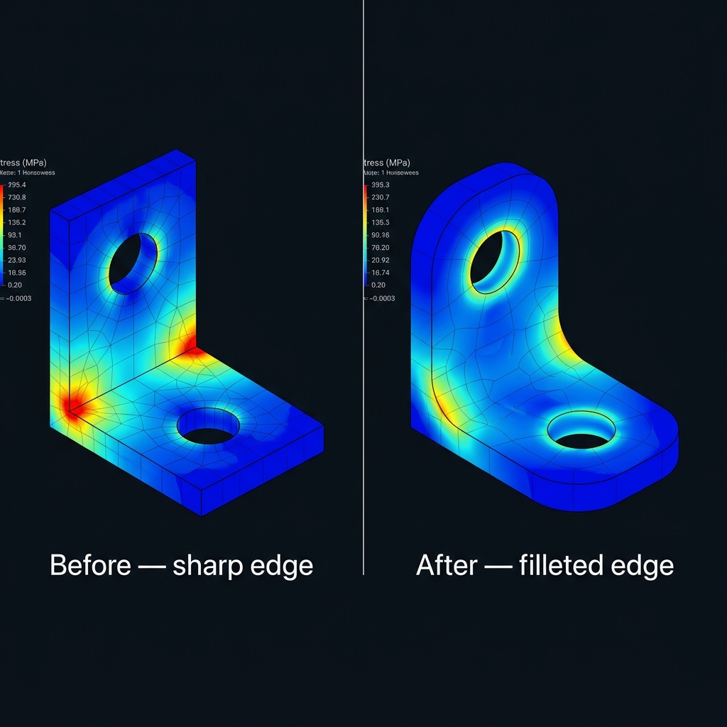
Two cheap changes typically pull that hotspot down without changing the part's function at all: adding a small fillet around the hole instead of a sharp machined-looking edge, and nudging the hole slightly further from the loaded end so it sits outside the highest-moment region. Neither change costs extra material or print time worth mentioning — but neither one is obvious just by looking at the model. It only becomes obvious once you see where the color turns red.
Where this method still has limits
A quick browser stress check is not a substitute for physical testing on anything where failure has real consequences — a load-bearing jig on a production line, a drone arm, a part near a person. Keep these limits in mind:
- Static loads only, by default. A linear static solve tells you about a steady load applied once. Drops, impacts, vibration, and repeated cyclic loading (fatigue) behave very differently and need different analysis types — a part can pass a static check and still fail after a thousand cycles of the same "safe" load.
- Material data is an approximation. PLA, PETG, and ABS all have published strength values, but your actual print — its temperature, speed, infill, and layer adhesion — will vary from the datasheet. Build in margin; don't design to exactly factor of safety 1.
- Geometry simplifications matter. Infill patterns aren't usually modeled explicitly — most tools treat the part as solid material, which is conservative for a part with less than 100% infill (the real part is *weaker* than the simulation, not stronger).
None of this makes the check pointless — it just means the result is a strong signal, not a certificate. For the overwhelming majority of maker and hobbyist parts, "does the hotspot look dangerous, and is the factor of safety comfortably above 1" is a far better filter than printing it and finding out.
The real value: catching it before the filament is spent
The whole point of doing this before printing is cost. A failed print costs filament, printer time, and — if it's a part you needed today — a schedule. A stress check costs a couple of minutes in a browser tab you already had open. Upload the STL, constrain it the way it'll actually be mounted, apply the load you actually expect, and look at where the color turns red before you look at where the plastic actually cracked.
Talk it through with someone
Not sure how to constrain a tricky mount, or whether your factor of safety is good enough given the layer orientation you're printing in? Drop the model in Discord or Telegram and ask the WebCAE community — other makers and engineers who've run this exact check before will tell you what they'd change. It's also the fastest way to hear about new analysis types as they ship off the roadmap.