FEA vs. Simplified Beam Calculators: When Do You Actually Need a Full Mesh?
Beam calculators are fast and accurate — for beams. Here's exactly where the Euler-Bernoulli assumptions break down, and a practical checklist for when to move to full 3D FEA instead.
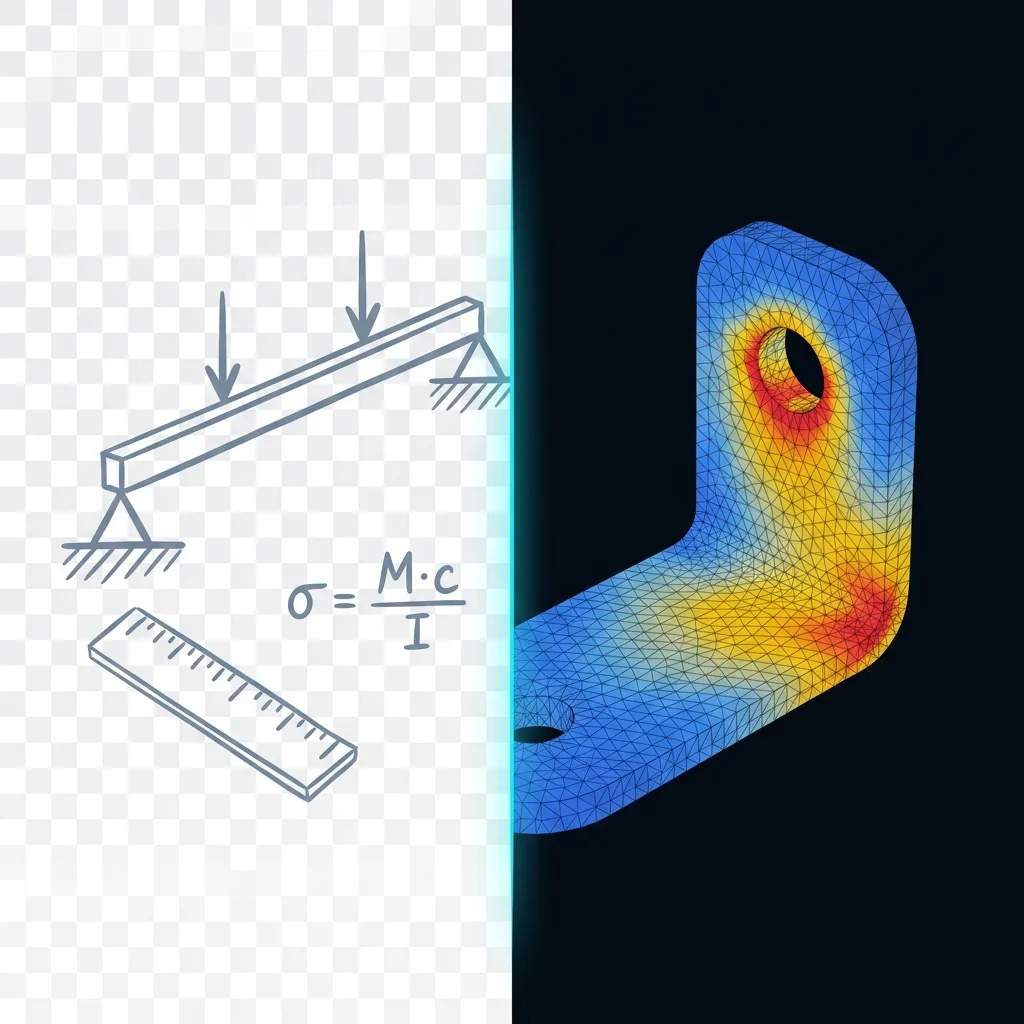
The gap nobody warns you about
Search "beam calculator online free" and you'll land on a dozen solid tools: put in a span, a load, a cross-section, get bending moment, shear, deflection. They're fast, free, and for what they do, accurate.
Search "finite element analysis online" and you land somewhere else entirely: full 3D solvers, mesh generation, von Mises stress fields, factor of safety maps.
Between these two categories is a gap most engineers fall into without noticing: a beam calculator gives you a confident, precise-looking number for a problem it was never built to represent. The number isn't wrong — it's just answering a simpler question than the one you're actually asking.
This article is about knowing which question you're asking.
What a beam calculator actually computes
Classical beam calculators are built on Euler-Bernoulli beam theory (or Timoshenko, for shorter/thicker beams). The underlying assumptions:
- The cross-section is prismatic — constant along the length, or changes in a way the tool explicitly supports (stepped sections at best).
- Plane sections remain plane — no out-of-plane warping, no local buckling.
- Loads are applied as idealized point forces, moments, or uniform distributed loads, on a 1D line representing the beam's neutral axis.
- Material is linear-elastic, isotropic, homogeneous.
- There are no stress risers: no holes, no fillets, no welds, no sudden section changes.
Under these assumptions, the math is exact (or very close to it) — that's why the results feel authoritative. For a real prismatic beam under a simple load case (a shelf bracket, a straight steel joist, a cantilevered arm with no cutouts), a beam calculator's answer and a full 3D FEA answer will converge closely, because the calculator's assumptions actually hold.
The problem starts when they don't.
Where the assumptions break
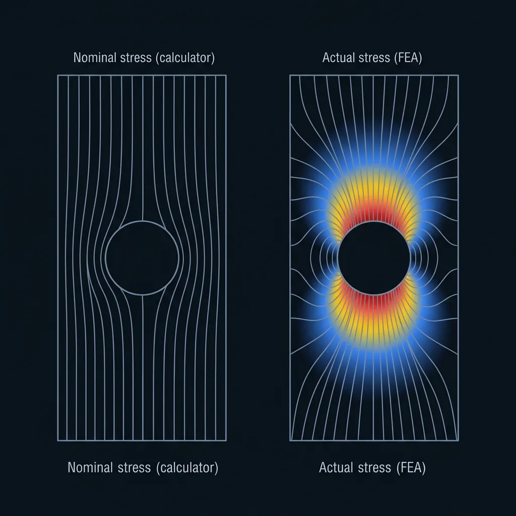
A few common real-world cases where a 1D beam idealization quietly stops being valid:
1. Stress concentrations. Any hole, fillet, notch, keyway, or sharp internal corner creates a local stress spike that a nominal-stress beam calculator cannot see — it computes average stress across a section, not the peak at a geometric discontinuity. The ratio between peak and nominal stress is the stress concentration factor (Kt), and for a small hole in a plate under tension, Kt is about 3 — meaning the real peak stress can be three times higher than what the calculator reports. A part that "passes" a hand calculation with a factor of safety of 2 can, in reality, be right at yield.
2. Non-prismatic or complex geometry. Brackets with ribs, gussets, varying wall thickness, or 3D branching load paths don't reduce to a single beam axis. You can sometimes force-fit them into a beam model with heavily simplified assumptions, but at that point you're modeling a different, easier part — not the one you're building.
3. Multi-axial and combined loading. A beam calculator typically handles bending, shear, and axial load independently or in simple combination. Real parts often see combined bending + torsion + axial + thermal loads simultaneously, interacting in ways that a superposition of 1D formulas doesn't capture accurately, especially near geometric discontinuities.
4. 3D effects near supports and load points. St. Venant's principle says stress concentrations from a load application point or support decay within roughly one cross-section's depth of distance — but near that boundary, beam theory's assumptions don't hold, and if your feature of interest (a hole, a weld) sits close to a support, the calculator's answer there is unreliable.
5. Buckling and dynamic behavior. Simple calculators often don't touch local buckling, torsional-flexural buckling, or modal (natural frequency) behavior at all — these require a structural model that captures the actual 3D stiffness distribution.
6. Anything that isn't slender. Beam theory assumes length is significantly larger than the cross-sectional dimensions (a common rule of thumb is length-to-depth ratio above ~10). A short, stubby bracket or a plate-like part isn't a beam — it needs shell or solid elements, not beam elements.
A practical decision checklist
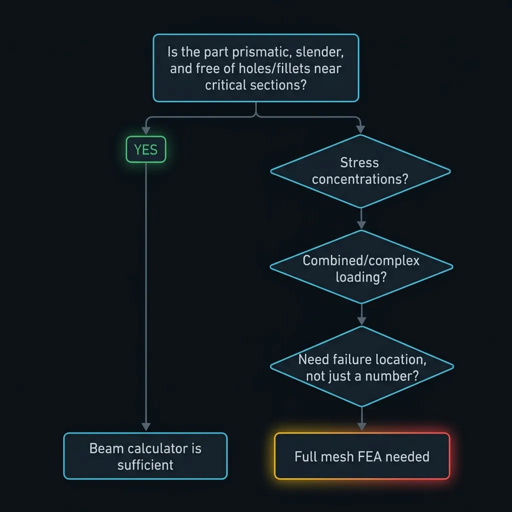
Ask these questions before trusting a beam calculator's number:
- Is the cross-section constant (or does the tool explicitly model the actual step/taper)? If not → full mesh.
- Are there holes, fillets, notches, or welds anywhere near the highest-stress region? If yes → full mesh, or at minimum apply a stress concentration factor by hand — but Kt values from handbooks assume idealized geometry too, so for anything non-standard, mesh it.
- Is the load combination more complex than a textbook case? (bending + torsion, off-axis loads, thermal + mechanical) → full mesh.
- Do you need to know *where* the part fails, not just *whether* it fails? A calculator gives you one number for one assumed critical section. FEA shows you the full stress distribution — including hotspots you didn't think to check by hand.
- Is the part central to a safety case, a customer deliverable, or a design you'll manufacture at scale? The cost of being wrong scales with consequence. A rough estimate for an early sketch is fine with a calculator; a part going into a certified product deserves a full model.
- Is the geometry inherently 3D (bracket, housing, casting, sheet metal with cutouts) rather than a long slender member? → full mesh, beam theory doesn't apply at all.
If you answered "full mesh" to any of these, a beam calculator isn't giving you a conservative estimate — it's giving you an answer to a question you didn't ask.
What a full mesh actually buys you
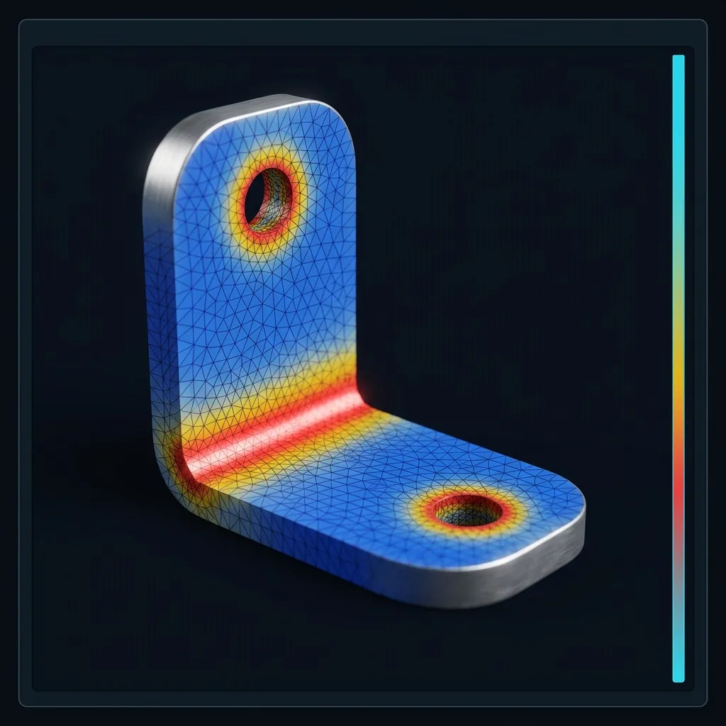
A full 3D (or shell) mesh with proper boundary conditions gives you things a beam calculator structurally cannot:
- A stress field across the entire geometry, not one number at one assumed critical section — so you find the hotspot even when it's not where intuition says to look.
- Real stress concentration values at holes, fillets, and joints, computed from the actual local geometry rather than a handbook Kt for an idealized case.
- Combined loading effects resolved correctly, because the model solves equilibrium in 3D rather than superposing simplified 1D formulas.
- A factor of safety map, so you know not just "does it survive" but "by how much, and where's the margin thinnest."
- The ability to iterate on geometry — round a fillet, thicken a rib, move a hole — and immediately see the effect on the actual stress distribution, instead of re-deriving a hand calculation for every change.
The honest tradeoff
None of this means beam calculators are obsolete. For a genuinely prismatic, slender member under simple, well-understood loading — a straight shelf support, a simple lever, a first-pass sizing estimate — a beam calculator is faster, requires no meshing, and gives you a defensible answer in seconds. Reach for full FEA when geometry, loading, or consequence complexity outgrows what a 1D idealization can honestly represent.
The failure mode to avoid isn't "using a calculator" — it's using one on a part it was never valid for, and trusting the precision of the output more than the validity of its assumptions. A calculator can hand you three significant figures for a model that's fundamentally the wrong shape.
Modern browser-based FEA tools have removed the traditional excuse for skipping the full model — no license, no install, no workstation — you can mesh and solve directly in a tab. Once the setup cost of "real" FEA drops to roughly the same as opening a calculator page, the right default shifts: reach for the full mesh whenever you're not certain the beam assumptions hold, not only when you're certain they don't.
Talk it through with someone
If you're not sure which side of the line your part falls on, don't guess alone. Drop the geometry in Discord or Telegram and ask the WebCAE community — other engineers who've made this exact call before will tell you whether it's worth the mesh. It's also the fastest way to hear about new analysis types as they ship off the roadmap.