From CAD Geometry to FEA Results
WebCAE takes a STEP model through geometry repair, meshing, materials, loads and boundary conditions to a solved structural result — one application, one model, no export round-trips between a CAD tool and a separate FEA package.
Runs in the browser. STEP import, meshing and solving are real, shipped functionality — not a demo.
CAD → Geometry check → Mesh → Loads → Solve → Results
Six stages, the same order every model goes through — from an imported STEP file to a stress field you can read.
What's actually in the product
Everything below is functionality you can use today, in the UI — not a roadmap item and not something available only through the scripting layer.
STEP import
AP203, AP214 and AP242, including multi-body assemblies — each solid becomes its own body in the model tree.
Boolean operations
Union across any number of bodies; cut and intersect between two bodies.
Geometry repair
A manual Repair operation (heal gaps, then merge same-domain faces) plus an automatic auto-fix option before meshing.
Fillet and chamfer
Pick edges directly in the 3D view and apply a radius or distance.
Sketch and extrude
2D sketches with lines, circles and arcs, geometric constraints (coincident, parallel, tangent, concentric and more), extruded as a new body, an addition, or a cut — including holes through a sketch with an inner loop.
Tetrahedral meshing
First- and second-order elements, curvature-driven sizing, local sizing zones, and adaptive refinement based on stress hotspots.
Materials
A material library plus custom entries — elastic properties, density, thermal conductivity, thermal expansion, and strength data for factor-of-safety checks.
Loads and boundary conditions
Force, pressure, distributed force, acceleration, remote load and remote motion; fixed, pinned and coupled supports; rigid (RBE2) and general MPC equations.
Multi-body contact
Bonded, tied and penalty connections between parts in an assembly, frictionless nonlinear contact in the desktop build, plus geometric bonding at the geometry stage.
Analysis types
Linear static, modal, linear buckling, prestressed modal, and thermoelastic — all reachable from the same Solve step.
Results and post-processing
Von Mises and principal stress, displacement, reaction forces per boundary condition, factor of safety against a chosen strength criterion, and stress-hotspot detection.
Example: a bracket from STEP to stress field
A typical path through the workflow above, using a load-carrying bracket as the running example.
Import
The bracket arrives as a STEP file — a single part, or a small welded assembly of two or three bodies.
Clean up the geometry
Run Repair to heal any gaps left by the CAD export, then fillet the sharp internal corners that would otherwise concentrate stress artificially.
Mesh
Let the automatic tetrahedral mesher size elements from curvature, then add a local sizing zone around the mounting hole and the fillet, where the peak stress is expected.
Materials, loads and supports
Assign steel from the material library, fix the mounting holes, and apply the service load as a force or pressure on the loaded face.
Solve
Run a linear static analysis. For a bracket near a motor or pump, a modal run alongside it checks the first natural frequency against the excitation frequency.
Read the results
The von Mises stress field shows where the peak sits — typically at the fillet, not at the load point itself — and the factor of safety says how much margin is left there.
Live interactive models in WebCAE
Open pre-solved 3D FEA models directly in browser WebAssembly without installing software or requesting license files.
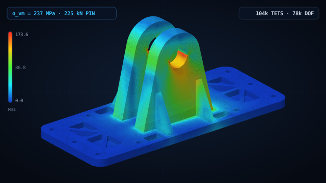
Dual-Lug Wing Attachment Fitting
Monolithic aerospace bracket under 185 kN limit tension load. Tet10 quadratic solid mesh, Kirsch hole stress concentration, and modal resonance checks in browser WASM.
104k Tet10 · σ_vm = 438 MPa · |u| = 0.74 mm · f₁ = 612 Hz
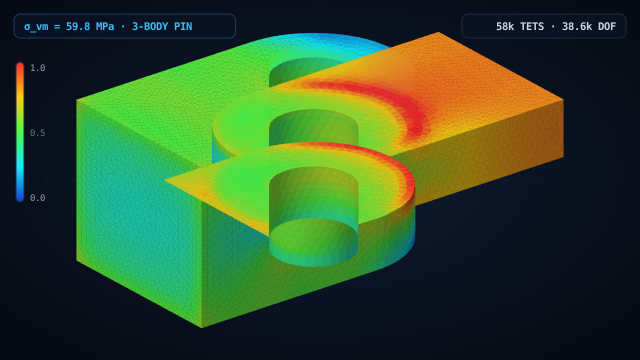
Aerospace Clevis, Lug & Shear Pin Joint
3-body actuator assembly (steel clevis, aluminum lug, stainless pin) with unilateral Mortar contact, pin bending under 20 kN tension, and genuine gap opening.
3 bodies · 25.1k Tet10 · 129k DOF · p_c = 138.6 MPa · σ_vm = 189.6 MPa
What each stage actually does
A closer look at the same six stages, in the terms the UI uses.
Import
STEP (AP203/AP214/AP242) is read through OCCT. A multi-body STEP file becomes several bodies in the model tree, ready for per-body operations like boolean union or contact assignment.
Geometry preparation
Repair (heal small gaps, then unify same-domain faces), fillet, chamfer and boolean operations are available before meshing. An optional automatic geometry auto-fix runs as part of the Mesh step.
Mesh
The default mesher is Netgen, generating first- or second-order tetrahedra with curvature-aware sizing. Local sizing zones and, where the shape fits, hexahedral strategies are available for finer control.
Materials
Linear-elastic (or hyperelastic) properties, density, thermal conductivity and thermal expansion, plus strength values used for the factor-of-safety check in the results.
Loads and boundary conditions
Forces, pressures, distributed loads, accelerations, and remote loads/motions on one side; fixed, pinned, coupled and rigid (RBE2) or general MPC constraints on the other. Multi-body assemblies add contact: bonded, tied, penalty, or frictionless nonlinear contact in the desktop build.
Solve
Linear static, modal (natural frequencies and mode shapes), linear buckling, prestressed modal (accounts for a static preload), and thermoelastic analysis all run from the same Solve step.
Results
Displacement, von Mises and principal stress, reaction forces per boundary-condition entry, factor of safety, and automatic detection of stress-concentration hotspots, with optional local remeshing to resolve them.
What this workflow doesn't cover
Stated plainly, so nothing here reads as a promise that isn't backed by the product:
- IGES import exists in the engine but has no import button in the UI today — it's reachable only through the scripting/DSL layer.
- Nonlinear contact is frictionless only and runs in the native desktop build; friction is in development. In the browser, bodies are connected through bonded, tied and penalty formulations.
- Material models are linear elastic, bilinear elasto-plastic and Neo-Hookean hyperelastic — there are no creep, damage or advanced plasticity models.
- Analyses are static, eigenvalue-based, or steady-state — there's no transient/explicit dynamics, crash or drop-test simulation, and no fatigue or CFD.
- WebCAE isn't a certified solver and doesn't provide engineering sign-off — it supports design decisions, and larger assemblies may need the desktop build rather than a browser tab.
Questions
What CAD formats can I import?+
STEP — AP203, AP214 or AP242 — including multi-body assemblies, where each solid becomes its own body. IGES is supported by the underlying engine but not yet by a UI import button; STL isn't supported.
Do I need a separate CAD tool to prepare the geometry?+
Not necessarily. Repair, fillet, chamfer and boolean operations are available directly in WebCAE, along with a sketch-and-extrude workflow for simple new geometry (including holes). Revolve, sweep and loft are available too, but complex modeling such as full parametric assemblies is better done upstream in your CAD system and imported as STEP.
Can I model an assembly, not just a single part?+
Yes. Importing a multi-body STEP file gives you one body per solid, and you can connect them with bonded, tied or penalty contact, frictionless nonlinear contact in the desktop build, or with rigid (RBE2) and general MPC constraints.
What happens if I change the geometry after meshing?+
Sketch-based extrude features can be edited and recomputed — the body updates in place, keeping its color and identity in the tree. Recompute isn't available for every kind of geometric change (see Limitations), so a substantial redesign is usually easiest to re-import as a fresh STEP file.
Which analysis types are actually available, not just planned?+
Linear static, modal, linear buckling, prestressed modal, and thermoelastic — all reachable from the Solve step today. There's no transient dynamics, explicit crash/impact, fatigue, or CFD.
How do I know the solver's numbers are right?+
The verification suite compares WebCAE's results against NAFEMS and MacNeal–Harder benchmarks and closed-form analytical solutions, case by case, with the deviation published for each one — including the Timoshenko cantilever beam case linked below.
Try it on your own geometry
Import a STEP file and go through the same six stages yourself — no install, no license to configure.