Where the CAD side is going: sketches, features, assemblies
Our target is a solid mid-range mechanical CAD — roughly FreeCAD Part Design or basic Fusion 360 — not a SolidWorks competitor. Here is the sequence: constrained sketches, real features with history, proper assemblies, and one rule about how geometry is addressed that we will not bend.
WebCAE started as a solver with enough geometry handling to prepare a model. That is no longer where it stops: this month brought extrusion from lines and surfaces, body creation from closed loops, twelve repair and defeature operations, coordinate systems built by picking. The natural question is how far this goes.
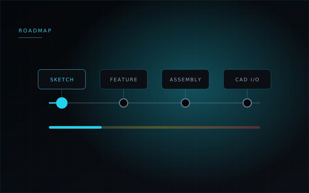
So here is the plan, published as a plan rather than as a promise. The target is a competent mid-range mechanical CAD — comparable to FreeCAD Part Design or basic Fusion 360 — without pretending we will match a full SolidWorks on advanced surfacing, sheet metal or production drawings. The pipeline we are building toward: sketch → constraints → profile → feature → body → assembly → CAD exchange → analysis.
It builds on what is there, not beside it
A design rule for all of it: new capability goes into the existing Create, Modify, Import, Inspect and Display groups. No new top-level tab per CAD operation. The sketch panel gets extended rather than replaced, and the tools you use today keep their place.
There is also low-hanging fruit worth naming: the geometry kernel and the scripting language already do revolve, sweep, loft and IGES exchange. They simply are not exposed as ordinary CAD commands in the interface yet.
First: constrained sketches
The sketcher grows into four sections — geometry, modify, constraints and dimensions. Geometry means arcs, circles, splines, construction lines and projected edges alongside the current point, line and rectangle. Modify means trim, extend, offset, sketch fillets, mirror and pattern, driven by selection rather than by typing indices.
Constraints are the part that makes a sketch a sketch: coincident, horizontal, vertical, parallel, perpendicular, tangent, equal, concentric, midpoint, symmetric, collinear, plus dimensional ones — distance, angle, radius, diameter. And a solver status readable at a glance: fully constrained, under-constrained with the remaining degrees of freedom counted, or over-constrained with the conflicting constraints listed. Automatic constraint inference will be available, and switchable off — it will never add a constraint silently to someone who turned it off.
Then: features with a history
Revolve, sweep and loft become real features with explicit references — the axis of a revolve is a reference you pick, never something inferred from a bounding box or a surface normal. Holes get their own parametric feature with counterbore, countersink and thread options, validated before Apply, rather than being a boolean subtraction of a cylinder you positioned by hand.
Behind them, an editable feature tree: each node keeps its inputs, its parameters, its output body and its status, so a change upstream marks what is stale and recomputes it. Mid-range CAD is not possible without that chain, and the audit log we have today is a different thing that will not be conflated with it.
Then: assemblies that are actually assemblies
Today's groups are folders, and we are not going to let folders keep impersonating components. Real assemblies mean components and instances as distinct things: one part, several occurrences, geometry stored once and placement stored per instance. That distinction is not bookkeeping — for analysis, material and topology belong to the part, while position and contact pairing belong to the instance.
With them come mates — fixed, coincident, concentric, distance, angle to start — each with two explicit reference picks and no hidden fallback to a normal or a bounding-box direction. And a bill of materials that counts instances rather than unique solids, because that is the number that gets ordered.
The rule we will not bend
Every reference to a face, edge, vertex or body uses a stable topological identifier or the project's numeric journal. Addressing geometry by axis or bounding box is banned from the interface, the state, the saved file, the scripting language and the solver targets alike.
The reason is the failure mode. When an operation changes the topology, we keep the exact lineage the kernel gives us, re-attach only what is provably unchanged, and mark everything else as needing review. What we will not do is pick a replacement face by centroid, normal or bounding box as a quiet fallback. A boundary condition that silently relocates to a different face is the worst class of error in this product: the analysis succeeds, and it answers a question nobody asked.
And what is out of scope
Explicitly not in the near term: full PMI and GD&T, complex kinematic assemblies, Class-A surfacing, CAM and toolpaths, PLM integration, native Parasolid or JT reading without a commercial connector, and automatic reconstruction of a feature history from an arbitrary STEP file. Sheet metal will appear when its workflow works end to end, and until then it will not sit in the ribbon pretending otherwise.