Loads you can see before you apply them
A force is now one entry with a vector instead of three separate ones, arrows are drawn at the centroid of the entity and point outward, and the preview appears while you are still filling in the form. Plus edge loads, coordinate systems built by picking, and a normal constraint that refuses to quietly compute the wrong problem.
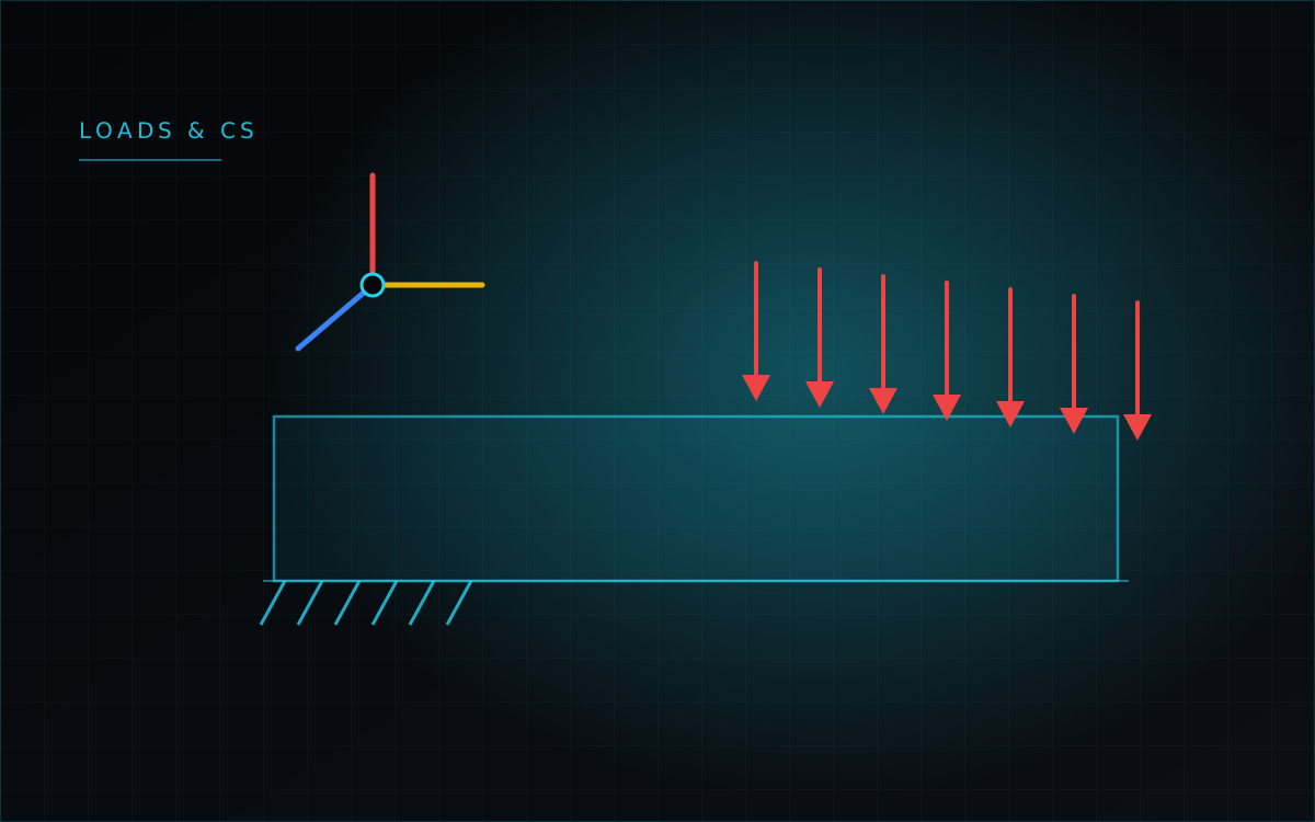
Boundary conditions are where analyses go wrong, and they go wrong silently. A load on the wrong face, a constraint that removes a degree of freedom you meant to leave free, a force applied along the global axis when you were thinking in the local frame — none of these produce an error. They produce a result, with the wrong physics. Most of this month's work on boundary conditions was about making them visible before the solve rather than debatable after it.
One force, one vector
A force with components along X, Y and Z used to be three separate entries in the tree. It is now a single entry carrying a vector, which is how an engineer thinks about it, and it is drawn in the viewport as a single arrow in the actual direction of the load rather than as three axis-aligned ones.
The arrow is oriented through the triad of whichever coordinate system the entry uses. So a force "along X" in a cylindrical system is drawn — and computed — radially. Concentrated forces are red, distributed ones orange, and the arrow length scales with the size of the scene rather than being a fixed number of millimetres that vanishes on a large model.
The preview arrives before the Apply button
While you are filling in the form, a draft entry is assembled and drawn live: pick the faces, type the magnitude, and the arrows are already on screen. Constraint arrows are now placed at the geometric centroid of the entity and always point outward — if the direction would put the arrow inside the body, it is flipped.
One bug worth admitting, because it is exactly the kind that silently misleads: on an assembly, a target is stored as a face index within its body, and the overlay was resolving that index against the first body it found with enough faces. The arrow could be drawn on a face of a completely different part. It is fixed, with a guard test, and the tree rows themselves were compacted — an icon, a short degree-of-freedom label, the magnitude and chips with the surface numbers, with the full description kept on hover.
Forces on edges
A load can now be applied to an edge or line, with the resultant distributed across the nodes that lie on it. It is not routed through the surface-load path and it is not divided by an area: 600 N on an edge with two nodes gives 300 N per node, and the resultant is preserved exactly. Edge loads work from the scripting language as well, and they are carried into the reaction post-processing, buckling reference loads and topology optimization.
Coordinate systems built by pointing at things
A coordinate system can be created from an entity rather than from typed numbers. Click a surface and two axes lie in it with Z along the normal. Click a line and the origin sits at its midpoint with X along it. Click a vertex and the axes stay parallel to global. From there you can define the axis directions by picking further points, or rotate around the local axes — any combination of the three, applied in sequence, with a reset for the angles.
The details matter here: arrow keys step angles by a hundredth of a degree and by a whole degree with Shift, and the hover plane shown while picking is now sized to the actual face under the cursor plus ten percent, instead of being a fixed square that either swamped a small part or floated inside a large one. Where a projection degenerates, the code falls back to an explicit reference direction rather than silently picking an arbitrary one.
Normal constraints that refuse to guess
Constraining displacement along the surface normal — a roller, or a symmetry plane — is the case where a plausible shortcut does real damage. When several constrained faces meet at a node, the tempting move is to average their normals. That is wrong: averaging the normals of two symmetry planes lets the node slide out of both along their line of intersection, which means computing a different problem with no message at all.
Instead the constraints at a node are solved as a small system by full Gauss-Jordan elimination with pivoting. Two nearly parallel normals produce a degenerate second row: if it is genuinely redundant it is dropped, and if it is contradictory it raises a warning. Two orthogonal normals both survive, because two symmetry planes are legitimate physics. Three of them pin the node completely. The nodal normal itself is weighted by the interior angle rather than by face area — the area weighting was measured and rejected because it failed its own acceptance criterion.
Two practical fixes came with it. A model held only by normal constraints now counts as constrained, so the Solve button is no longer blocked. And loading purely by prescribed displacement — inflating a cylinder by a specified radial movement, with no force anywhere — now counts as a load, so preflight stops refusing to run a perfectly well-posed problem.
These constraints have analytical backing: a thick-walled cylinder in a rigid casing matches the Lamé solution to 0.48%, the same cylinder driven by a prescribed normal displacement of 50 µm matches to 0.24% while reproducing the imposed displacement itself to within a few millionths of a percent, and a quarter-model of the plate-with-hole problem, cut by two symmetry planes, agrees with the full model to 1.38%.