Inspect pre-solved models in your browser in 2 seconds (up to 300k DOF) or solve 1.5M+ DOF assemblies 100% offline on Windows and macOS.
Heat Exchanger Staggered 5-Tube Bundle Cross-Flow & Vortex Wake (CFD)
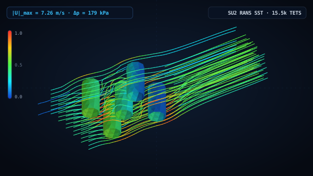
3D turbulent cross-flow (RANS k-ω SST, water U_in = 2.5 m/s) across a 3-row staggered bundle of five Ø44 mm heat exchanger tubes, capturing inter-tube jet acceleration up to 7.26 m/s (2.90× U_in), wake recirculation zones, and Δp = 179.1 kPa hydraulic resistance.
Shell-and-tube heat exchangers and steam generators arrange tubes in staggered (triangular) pitch patterns so the wake behind each upstream tube splits into high-velocity jets that impinge directly on the leading face of the next row, maximizing convective heat transfer at the cost of higher pressure drop. This 3D CFD model represents a rectangular cross-flow channel (460 × 220 × 90 mm) containing a 3-row staggered array of five Ø44 mm tubes (2 tubes in Row 1 at X = −20 mm, 1 central tube in Row 2 at X = +45 mm, and 2 tubes in Row 3 at X = +110 mm). Water enters at U_in = 2.5 m/s (Re_D ≈ 1.1×10⁵). Solved with native SU2_CFD (k-ω SST), the simulation captures sinuous acceleration through the narrow inter-tube gaps up to 7.26 m/s (2.90× inlet velocity), separated recirculation wakes behind each cylinder, a bundle pressure loss of Δp = 179.1 kPa, and 1,266.9 N of total hydrodynamic drag on the tube bank.
1. Geometry & FEA Mesh
- •Single B-Rep fluid domain (D_fluid = Channel − 5 Staggered Tubes): 460 mm streamwise length (X ∈ [-140, 320] mm), 220 mm width (Y ∈ [-110, 110] mm), and 90 mm spanwise depth (Z ∈ [-45, 45] mm).
- •Three-row staggered bank of five Ø44 mm circular tubes (transverse pitch S_T = 100 mm, longitudinal pitch S_L = 65 mm).
- •Unstructured 3D tetrahedral mesh: 15,480 tetrahedra and 3,755 nodes (volume discretization error 0.39%).
- •Working fluid: water (ρ = 998.2 kg/m³, μ = 1.002×10⁻³ Pa·s) with Menter k-ω SST turbulence model.
2. Loads & Boundary Conditions
- •Channel inlet face at X = −140 mm (surface number 1): uniform water velocity U_in = 2.5 m/s along +X ([1, 0, 0]).
- •Channel outlet face at X = +320 mm (surface number 11): static gauge pressure p_out = 0 Pa.
- •Top and bottom spanwise bounding planes at Z = ±45 mm (surfaces 3 and 4): symmetry / periodic slip planes.
- •Channel side walls (Y = ±110 mm) and all five cylindrical tube walls (surfaces 2, 5, 6, 7, 8, 9, 10): viscous no-slip walls (u = 0).
3. Simulation Results & Findings
- ✓Cross-flow constriction between the staggered tubes and channel walls accelerates water jets up to |U|_max = 7.26 m/s (2.90× inlet velocity).
- ✓Total static pressure drop across the 3-row staggered bundle is Δp = 179.1 kPa, with stagnation peaks of +188.6 kPa on the upstream tubes and suction troughs of −54.2 kPa on the tube flanks.
- ✓Hydrodynamic drag integrated across the tube walls and duct is F_D = 1,266.9 N, while separated shear layers behind all 5 tubes reach |ω|_max = 535.7 s⁻¹ and Q_max = 6.26×10⁴ s⁻² (mass imbalance 0.61%).
Thermal and power-plant engineers use WebCAE CFD to compare inline vs. staggered tube pitches, quantify shell-side pressure drops, and extract hydrodynamic tube forces for flow-induced vibration checks.
14 days of full Pro access. The first charge occurs only after 14 days unless canceled beforehand.
- ✓14-Day Trial ($0 Today) (cancel anytime)
- ✓Up to 1.5M+ DOFs (direct sparse solver)
- ✓Native Windows & macOS Apps (100% offline)
- ✓Nonlinear Contact & Buckling (Kσ, MITC4, RBE2/RBE3)
Ask an Engineer About Your Model
Describe your part, load case, or CAD format — we reply within 2 business hours.
Want an instant answer on FEA theory or this model?
Click the AI chat button in the bottom-right corner to ask about boundary conditions, stress criteria, mesh convergence, or DSL scripting.
More Engineering Simulation Cases
Twin-Inlet Swirl Mixing Collector & Header Manifold (CFD)
1.5 MW Wind Turbine Cast Rotor Hub
Pelton Hydro Turbine Runner (12 Buckets)