Inspect pre-solved models in your browser in 2 seconds (up to 300k DOF) or solve 1.5M+ DOF assemblies 100% offline on Windows and macOS.
Kort Nozzle Ducted Marine Thruster with 3 Pitched Blades: Helical Wake (CFD)
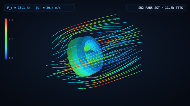
3D hydrodynamic flow (RANS k-ω SST, water U_∞ = 6.0 m/s) through an annular Kort nozzle shroud, streamlined hub, and three 28°-pitched hydrofoil stator/thruster blades, resolving duct flow acceleration up to 29.4 m/s and 16.1 kN axial hydrodynamic force.
Tugboats, ROVs, dynamic-positioning thrusters, and pump-jets enclose the rotor/stator blades inside an annular Kort nozzle shroud to accelerate axial inflow and suppress tip losses. This 3D CFD model places a complete ducted thruster unit—comprising a streamlined nose/tail hub (R_hub = 28 mm), three hydrofoil blades pitched at 28° spaced 120° apart, and a flared annular nozzle shroud (R_in = 84 mm, R_out = 108 mm)—inside a 580 × 360 × 360 mm open-water test channel at U_∞ = 6.0 m/s. Solved with native SU2_CFD (k-ω SST), the simulation captures flow acceleration through the blade passages up to 29.42 m/s, strong tangential swirl imparted by the 28° blades into the downstream wake, and a total axial hydrodynamic load of 16.09 kN.
1. Geometry & FEA Mesh
- •Single B-Rep fluid control volume (D_fluid = Channel − ThrusterUnit): 580 mm length (X ∈ [-200, 380] mm) and 360 × 360 mm cross-section.
- •Unified internal thruster geometry: central hub with conical nose/tail caps, three 28°-pitched blades (120° spacing), and annular Kort nozzle shroud ring.
- •Unstructured tetrahedral mesh: 11,755 tetrahedra and 2,727 nodes (volume error 0.05%).
- •Working fluid: water (ρ = 998.2 kg/m³, μ = 1.002×10⁻³ Pa·s) with Menter k-ω SST turbulence closure.
2. Loads & Boundary Conditions
- •Channel upstream inlet face at X = −200 mm (surface number 1): uniform water velocity U_in = 6.0 m/s along +X ([1, 0, 0]).
- •Channel downstream outlet face at X = +380 mm (surface number 6): static pressure p_out = 0 Pa.
- •Four outer test-section side walls at Y = ±180 mm, Z = ±180 mm (surfaces 2, 3, 4, 5): slip / symmetry boundary conditions.
- •All internal hub, 3 pitched blades, and Kort nozzle shroud surfaces (23 faces): viscous no-slip wall (u = 0).
3. Simulation Results & Findings
- ✓Flow constriction inside the annular nozzle and blade passages accelerates water up to |U|_max = 29.42 m/s (4.90× freestream velocity).
- ✓Total axial hydrodynamic force acting on the shroud, hub, and 3 blades is F_X = 16,089.4 N (16.09 kN) with an overall channel pressure drop of Δp = 514.8 kPa.
- ✓The 28° blade pitch deflects axial streamlines into a distinct swirling helical wake behind the tail cone with peak vorticity |ω|_max = 813.3 s⁻¹ and Q_max = 9.06×10⁴ s⁻².
Naval architects and marine propulsion teams use WebCAE CFD to evaluate nozzle shroud profiles, stator vane pitch angles, and cavitation low-pressure peaks before transferring hydrodynamic pressures to structural FEA.
14 days of full Pro access. The first charge occurs only after 14 days unless canceled beforehand.
- ✓14-Day Trial ($0 Today) (cancel anytime)
- ✓Up to 1.5M+ DOFs (direct sparse solver)
- ✓Native Windows & macOS Apps (100% offline)
- ✓Nonlinear Contact & Buckling (Kσ, MITC4, RBE2/RBE3)
Ask an Engineer About Your Model
Describe your part, load case, or CAD format — we reply within 2 business hours.
Want an instant answer on FEA theory or this model?
Click the AI chat button in the bottom-right corner to ask about boundary conditions, stress criteria, mesh convergence, or DSL scripting.
More Engineering Simulation Cases
5-Blade Marine Propeller Ø4.2 m
180 m Cargo Ship Hull with Framing
Swept UAV Wing with Tip Winglet: Wingtip Vortex & Lift/Drag (CFD)